Thursday 24 January 2013
Wednesday 23 January 2013
Denso alternator
Got sick and tired of doing panelling work. Also I managed to source a nice shiny new 40AMP Denso lightweight alternator over Christmas so decided to start taking a look at mounting that.
On the Tiger I'd reused the Lucas alternator and only had sensible space on the exhaust side. With the Fury there's more space on the inlet side and mounting the alternator there reduces the complexity in terms of extra pulleys etc. Also better from a heat point of view.
First job with the alternator was to remove the V belt pulley and replace it with a 6 rib (6PK) pulley to match the other pulleys on the engine.
Behind the V pulley is a spacer, seen middle top in the picture below. In comparison the 6PK pulley has a 'shoulder' but this isn't the same depth as the space, see later picture which shows the thickness of the 6PK pulley. A small spacer is therefore needed and one was made by carefully drilling out a suitable thickness and diameter washer. Also the shaft of the alternator is 15mm OD however the 6PK pulley is 17mm ID. Middle bottom shows the 'sleeve' to make up the 2mm difference:

The picture below shows a comparison between the V pulley plus spacer and the 6PK pulley, sleeve and washer.

The 6PK pulley is 60mm OD which is slightly larger than the V pulley so should be fine from an RPM point of view:

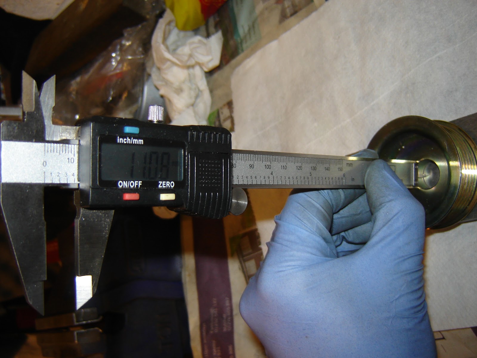
Depth of the pulley to shoulder is 11mm:

Next job was to identify where to mount the alternator on the inlet side. I've seen a few people who have used the bottom two air-conditioning pump mounts and the threaded hole beside the water pump so thought I'd go with these.
Objective is to have the alternator solidly mounted and make the top pulley manually adjustable to take up the belt tension (there's insufficient space to use a Ford Focus type automatic adjuster on the inlet side of the cylinder head).
For the top alternator mount decided to use a piece of angle iron (mild steel) drilled carefully so that it locks tight to the block by the water pump. In turn this was drilled and a spacer added to bolt into the threaded top mount on the alternator body:

For the bottom mount used a couple of pieces of scrap, drilled and shaped. Then mocked up the position and got the alternator square vertically and horizontally based on the crankshaft pulley. Then out came the MIG welder, tacked, removed and finish welded on the bench.
Final job will be to paint both parts when I get a number of other parts together to all be painted at the same time:

Pleased with the result. Just need to sort out the top adjuster pulley and source a suitable length 6PK belt. Also now need to source an oval alternator plug but I've ordered an MG engine loom which should have the required plug along with some others I'm after.
Must get back to that panelling... (eventually since I'm expecting some parts to arrive from Steve @ Fury)
On the Tiger I'd reused the Lucas alternator and only had sensible space on the exhaust side. With the Fury there's more space on the inlet side and mounting the alternator there reduces the complexity in terms of extra pulleys etc. Also better from a heat point of view.
First job with the alternator was to remove the V belt pulley and replace it with a 6 rib (6PK) pulley to match the other pulleys on the engine.
Behind the V pulley is a spacer, seen middle top in the picture below. In comparison the 6PK pulley has a 'shoulder' but this isn't the same depth as the space, see later picture which shows the thickness of the 6PK pulley. A small spacer is therefore needed and one was made by carefully drilling out a suitable thickness and diameter washer. Also the shaft of the alternator is 15mm OD however the 6PK pulley is 17mm ID. Middle bottom shows the 'sleeve' to make up the 2mm difference:

The picture below shows a comparison between the V pulley plus spacer and the 6PK pulley, sleeve and washer.

The 6PK pulley is 60mm OD which is slightly larger than the V pulley so should be fine from an RPM point of view:

Depth of the pulley to shoulder is 11mm:
Next job was to identify where to mount the alternator on the inlet side. I've seen a few people who have used the bottom two air-conditioning pump mounts and the threaded hole beside the water pump so thought I'd go with these.
Objective is to have the alternator solidly mounted and make the top pulley manually adjustable to take up the belt tension (there's insufficient space to use a Ford Focus type automatic adjuster on the inlet side of the cylinder head).
For the top alternator mount decided to use a piece of angle iron (mild steel) drilled carefully so that it locks tight to the block by the water pump. In turn this was drilled and a spacer added to bolt into the threaded top mount on the alternator body:

For the bottom mount used a couple of pieces of scrap, drilled and shaped. Then mocked up the position and got the alternator square vertically and horizontally based on the crankshaft pulley. Then out came the MIG welder, tacked, removed and finish welded on the bench.
Final job will be to paint both parts when I get a number of other parts together to all be painted at the same time:

Pleased with the result. Just need to sort out the top adjuster pulley and source a suitable length 6PK belt. Also now need to source an oval alternator plug but I've ordered an MG engine loom which should have the required plug along with some others I'm after.
Must get back to that panelling... (eventually since I'm expecting some parts to arrive from Steve @ Fury)
Wednesday 16 January 2013
Friday 11 January 2013
Catch up post 5
Next stage - underside floor panelling... (if I never see another piece of sheet aluminium...)
Chassis turned upside down and work started on marking up and drilling the remaing floor panels (the chassis already has lowered rear floor sections which are welded in steel panels). Worth noting that having two different drill bit sizes, pilot and final, along with two drills makes things alot easier (along with 'unpaid help').
Decided to have one of the two front floor panels re-made since it wasn't quite large enough and the overlap with the chassis rails was a bit limited (looking for a good watertight seal).
O/S panel being lined up:
 N/S panel lined up and 4 corners drilled :

O/S fillet piece, not originally supplied, but decided was worth doing. I'd seen other builds, without the lowered floor, where the large floor panel went all the way back and this included support for the side pods that far back:

N/S fillet piece - same story but caught in the act of domestic activities...

Once drilled, holes deburred (with a 13mm drill bit), pop rivets trial fitted and then all removed again the panels were then put aside for safe keeping (and to await painting or powder coating - inside of floor panels).
Chassis put back the right way up and O/S outside panels to look at. After much adjusting, fiddling, masking tape, marking, measuring and general mucking about the panels were where they seemed okay (note: need to buy shares in masking tape company...):

Where the two panels meet I decided not to overlap but instead to fit a trim piece over the join and seal it as well as the panels:

Need to get a picture of the overall effect but this shows the front panel (note: need to buy shares in pop rivet company as well):

Another trick that was figured out was to use a piece of wood on the drill bit. With the correct thickness this stops the drill bit hitting the inside of the chassis rail when it bursts through. It also stops the chuck of the drill marking the aluminium panel (if you're are bothered about that):

This is the final 'Catch up' post so as long as I keep disciplined then further 'as it's happening' posts should start to appear.
Chassis turned upside down and work started on marking up and drilling the remaing floor panels (the chassis already has lowered rear floor sections which are welded in steel panels). Worth noting that having two different drill bit sizes, pilot and final, along with two drills makes things alot easier (along with 'unpaid help').
Decided to have one of the two front floor panels re-made since it wasn't quite large enough and the overlap with the chassis rails was a bit limited (looking for a good watertight seal).
O/S panel being lined up:


O/S fillet piece, not originally supplied, but decided was worth doing. I'd seen other builds, without the lowered floor, where the large floor panel went all the way back and this included support for the side pods that far back:

N/S fillet piece - same story but caught in the act of domestic activities...

Once drilled, holes deburred (with a 13mm drill bit), pop rivets trial fitted and then all removed again the panels were then put aside for safe keeping (and to await painting or powder coating - inside of floor panels).
Chassis put back the right way up and O/S outside panels to look at. After much adjusting, fiddling, masking tape, marking, measuring and general mucking about the panels were where they seemed okay (note: need to buy shares in masking tape company...):

Where the two panels meet I decided not to overlap but instead to fit a trim piece over the join and seal it as well as the panels:

Need to get a picture of the overall effect but this shows the front panel (note: need to buy shares in pop rivet company as well):

Another trick that was figured out was to use a piece of wood on the drill bit. With the correct thickness this stops the drill bit hitting the inside of the chassis rail when it bursts through. It also stops the chuck of the drill marking the aluminium panel (if you're are bothered about that):

This is the final 'Catch up' post so as long as I keep disciplined then further 'as it's happening' posts should start to appear.
Saturday 5 January 2013
Catch up post 4
Next job was to panel the end of the passenger side footwell. Having researched a bit I have noticed that the older Fury chassis has a welded steel panel at the end of the footwell - rapidly concluded this would probably be a nicer solution.
Anyway having ordered the chassis pack with the pre-cut aluminium panels started to look at fitting the panel provided. Unfortunately found that the cutouts around the chassis rails etc. were too large (complex position for the panel in terms of intersecting chassis horizontals and verticals) and would provide large gaps through which water could make its way in (in spite of large quanities of sealant).
So decided to make up a template and have a new panel cut. This then got carefully fettled to fit as tightly as possible (managed to reduce the gaps to a millimetre or less). This included a trick of chamfering the edge of the aluminium to allow for the weld pools around joints and provide a tighter fit:


Then the exciting job of drilling, in some cases in tight locations for example at the bottom of the panel and around the side chassis rails. To do this involved employing a variety of different drill attachments. The result was the following:
 You'll notice the black pop rivets. I've seen on a couple of other build blogs that having a large shinny aluminium panel at the back of the engine bay sticks out like a sore thumb. On this basis I decided to spray the panel to match the chassis colour so it would blend in:
All ready to fit. I've decided to hold off the final fitting, sealing and rivetting, until I have all the panels drilled and trimmed.
Anyway having ordered the chassis pack with the pre-cut aluminium panels started to look at fitting the panel provided. Unfortunately found that the cutouts around the chassis rails etc. were too large (complex position for the panel in terms of intersecting chassis horizontals and verticals) and would provide large gaps through which water could make its way in (in spite of large quanities of sealant).
So decided to make up a template and have a new panel cut. This then got carefully fettled to fit as tightly as possible (managed to reduce the gaps to a millimetre or less). This included a trick of chamfering the edge of the aluminium to allow for the weld pools around joints and provide a tighter fit:


Then the exciting job of drilling, in some cases in tight locations for example at the bottom of the panel and around the side chassis rails. To do this involved employing a variety of different drill attachments. The result was the following:

Thursday 3 January 2013
Catch up post 3
With the steering rack in place I was then able to look at the steering column (late Sierra adjustable column):

I plan to reuse the switch gear, wheel (for IVA at least) and cowling. Initially I'll leave the column adjustment disabled but I may later look to at least use the 'in-out' adjustment if it's useful.
On the basis of this I needed to ensure that the sliding section of the column is at it's 'shortest' position so that the steering wheel can be pulled towards the driver. To enable the top part of the column to move towards the driver requires modification of the column mounting plate to provide a slot for the adjuster to move through (note mounting plate is actually mounted on top not underneath as shown):

The steering column adjuster bracket needed to be reversed so that it could then mount to the plate above. Picture also shows the column after stripping, cleaning and painting - trial fitted with lower bearing and column link:

The column link needed cutting - I decided to cut diagionally so that the original orientation/alignment could be establish:

The column link then needed lengthening to reach to the steering rack. To do this a suitable ID pipe was used with two holes drilled and tapped for screws to lock the two link ends at the correct length and position (to give reasonable clearance over the chassis rail - approx. 15mm):

With the above sorted the steering column lower bearing mounting plate could attached to the pedal box by drilling and bolting through (the piece of wood and string is to hold up the pedals which were also trial fitted at the time):

The steering column link, all set up, was then sent off to a local welder to have a better quality, and seamless, steel tube used to attach the link ends (welded, cleaned and ready for painting):

Next decided to sort out a removable aluminium cover for the pedal box - drilled and rivnutted:

Cleaned, keyed and painted:

Wednesday 2 January 2013
Catch up post 2
Second of a couple of catch up posts.
As part of trial fitting all the parts supplied in the chassis pack got round to the handbrake. It quickly became apparant that there was an issue with the operation since the eyelet on the end of the handbrake itself wasn't welded on square:

Following some angle grinder work the eyelet was thinner but square - still sufficiently thick to do the trick:

Next a standard Sierra handbrake cable (drum) trial fitted and operation checked:

As others have found the cable itself rubs against the middle pillar on the nearside of the transmission tunnel. I'll need to sort out something to attach to the pillar for the cable to rub against instead of the chassis metal - probably some sort of rounded plastic bar (anyway that will need to be sorted later).
Next, attention turned to trial fitting the steering rack (Escort quickish rack - 2.9:1) - nice alloy rack mounts:

Tuesday 1 January 2013
Catch up post 1
Alot's happened since the last post, in September, and although I've had some time to work on the car I haven't found time to post updates (so this is the first of a number of catch up posts - hopefully).
The chassis set up in it's new home:

The first major job was to trial fit all the suspension parts (although the rear uprights and front/upper wishbone ferrules haven't yet arrived from Fury Sports Cars - FSC).
First issue encountered was that the front lower wishbones wouldn't accept the Land Rover balljoints (the threads needed cleaning out).
Conversation with Steve (FSC) and a few days later a suitable tap arrived in the post.
 The thread can only have been clogged with the anticorrosion material since it cleared very quickly with the tap.
To fit the suspension parts most of the mounting holes needed the powder coat clearing

This was done carefully using a round file.
Some photos of the results:


The chassis set up in it's new home:

The first major job was to trial fit all the suspension parts (although the rear uprights and front/upper wishbone ferrules haven't yet arrived from Fury Sports Cars - FSC).
First issue encountered was that the front lower wishbones wouldn't accept the Land Rover balljoints (the threads needed cleaning out).
Conversation with Steve (FSC) and a few days later a suitable tap arrived in the post.

To fit the suspension parts most of the mounting holes needed the powder coat clearing

This was done carefully using a round file.
Some photos of the results:


Subscribe to:
Posts (Atom)