Monday 18 March 2013

Front diff mount spacers

FSC supplied spacers for the front diff mounts however they did't fit - both were too short and too long... (if you see what I mean).

In preference to using a set of washers decided to source some aluminium tube (obviously thick wall):

Cut and power filed carefully for a snug fit (O/S shown):

Nice solid fit and very tidy looking (N/S shown):

Just needs some copper slip sprayed inside to protect against corrosion and then torquing up.

Saturday 16 March 2013

'In Suspension...'

Having got the diff in decided to fit as much of the suspension as currently possible, turned out there was quite a lot that could be fitted.

Front end with Protech shocks, Escort quick rack and steering column extension in position:


Nearside front

Side view of upright. Decided to use washers (to protect the powder coat) and temporarily plain nuts (to preserve the nyloc nuts) until the she's got wheels and is on the ground.

Not yet sure how I'll torque up the top ball joint (or even what the torque should be). The rocker arm is shown set as far back as possible to improve self centring of the steering (shock also needed setting back to match):

Viewed from the front:

Offside front

Similar story although top rocker washers need adjusting since they're not yet the correct combination of sizes to take up the fore/aft play:

Viewed from the front:

Offside rear

Once the handing of the rear uprights and top wishbones were figured out it was pretty straight forward to assemble the rear set up. In this case it's a drum brake set up which means the uprights are fitted with the flat face pointing to the rear. With the lower mounting for the uprights it took a couple of tries to get right the number and position for the washers so that the upright is held solidly when the long lower bolt is tightened:

It's going to be a pain to set up the camber and toe in. For the latter the upright needs to be moved clear enough to allow the front rose joint to be screwed in or out (see bottom left in the following picture). This means removing virtually completely the lower bolt, and therefore the spacing washers etc.:

In the above picture you can see how the front bolts on the top and bottom wishbones need to be oriented so that once the rear panel is fitted the bolts can still be removed (nuts to the front - so to speak). Get this wrong and removing the wishbones would be a nightmare.

Nearside rear

The only difficulty on the nearside was that the lower mounting holes on the upright needed filing out a little since one metal tube hadn't been welded on quite square and therefore wasn't aligned for the bolt to go through easily.

The rear end then looked like this:
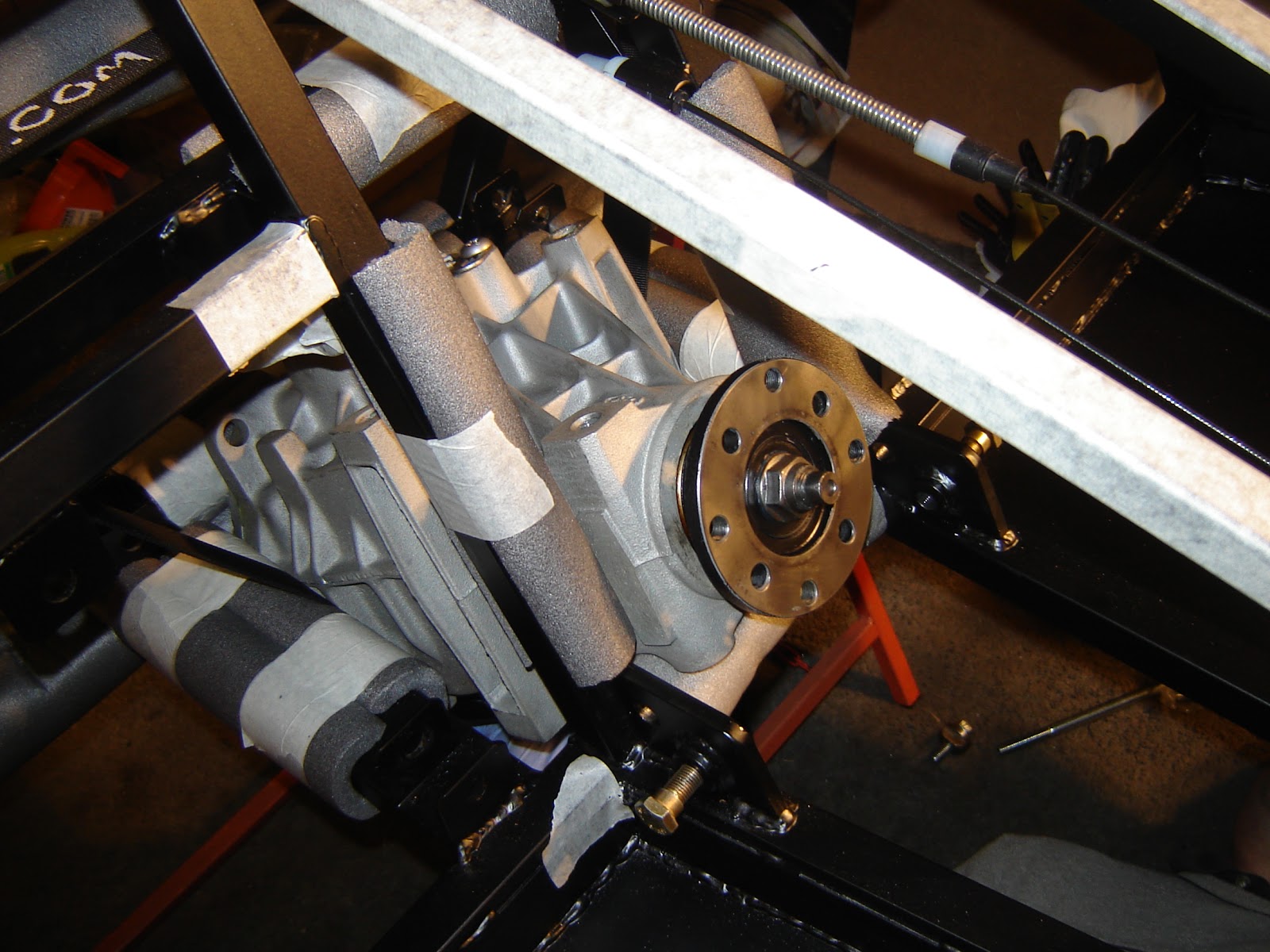

Drive shafts

With the drum brakes Sierra Tripod drive shafts are used. These are modified (shortened) and rebuilt by FSC. The following picture shows what the rear end looks with the drive shafts fitted:

However it quickly became clear that there was a problem with the length of the offside drive shaft since it didn't protrude through the upright enough to be compressed as the bearing carrier is bolted on:

Looks like it's back to FSC for the O/S drive shaft.

On the offside a quick experimental assembly of the upright spacer, brake back plate, bearing carrier, hub and drum to prove it all fits together - this showed up that the four bolts through the upright were too short by about 10mm so will need to sort these as well - looks nice though:


Thursday 7 March 2013

Diff

With the chassis the right way up, hopefully for good, decided the diff should go in next. The nice and shiny 3.62 open diff is fresh from BGH Geartech:

Before starting the powder coating needed a little bit of protection... Shares also now in pipe lagging! In the following picture the chassis stand, seen bottom right, needed to be moved to the left so that there was enough room to get the diff in:

The process of fitting started by getting the unpaid help involved and then turning the diff on its side. It is then inserted upwards from the bottom until it's as high as possible and then tilting it forwards:
 
The use of a luggage strap really helped to control the process of moving the diff around inside the chassis framework that exists where the diff is situated:


View from the front:

Once the diff was in position on its side, but supported by the strap, the two pairs of hands made the next stage relatively easy. The diff then needed wiggling around and rotating back into the upright position:

Having measured the diff top mount beforehand the expectation was that it probably wouldn't fit in easily. Sure enough it was about 1mm too wide. Managed get the PowerFile far enough into the chassis framework to grind off enough material from one end of the diff's top mounts - took two attempts to get it right for a snug fit into the chassis mounts.

After some persuasion in went the top bolt mount bolt, although narrowly missing the top wishbone mount (it's very tight). The current rear bolt and front two mount bolts are all too short and the front mount spacers aren't right, but apart from that it's perfect:

I'll look to sort out the correct length bolts later.

Wednesday 6 March 2013

Front rocker arms

The front top rocker arms have nylon top hats fitted each side through which a steel tube ferrule is fitted. The idea is to have a tight fit on the ferrule so that there's no slack in the front suspension. To do this the nylon top hats need to be reamed out - but by just the right amount.

To do this a reaming tool was made up using a section of scrap steel tube, slotted, sand paper fitted into the slot and wrapped around to make it a reasonable fit in the top hat opening. With this fitted into a drill and rotated in the correct direction it created a sanding effect to open up the holes:

Each side of both rocker arms was then reamed gradually and the steel ferrule checked for fit regularly:

A bolt was then fitted through the ferrule tube and tightened up so that each rocker arm could be put in a vice. With the bolt held in the vice the ferrule couldn't move and the resistance on the top hat bushes and freedom of movement could be checked:

The lengths of the ferrule tubes may need modifying to allow them to fit into the chassis mounting points.

Monday 4 March 2013

Modifying Rear Uprights & Sealing Underside Panels

Rear uprights

Unfortunately after some experimenting with the fitting of the rear hubs and spacer plates discovered there was a problem with one of the uprights. As can be seen in the picture below, the upright on the left has one of the driveshaft hub mounting holes too close to the upright's side plate. There isn't enough clearence for the bolt head:

After a bit of head stratching decided it was best to grind away the side plate a little to create the clearance needed - out came the Dremel with a sanding wheel attached - just the right size for the job:

The plan will be to get the uprights powder coated for the exposed metal should be sorted.

Floor panelling

Having got the floor panels back from powder coating and getting ready for sealing and riveting realised I hadn't read the build manual - doh! The build manual is fairly clear that the preference is for the large pop rivets to be used on these panels (for added strength if someone tries standing) - the panels had been drilled for the small pop rivets so out came the drill again.

A little time later, and with some unpaid help, all sorted. Also shown in the photo below are the front fillets which I think I'll get powder coated as part of a second batch of parts to be done:

Sealing the underside panels

Since getting the first panels back from powder coating I'd been waiting for improved temperatures but finally ran out of patience and warmed up the garage a bit. Sikaflex 221 datasheet indicates not to apply below 5*C or above 45*C (the latter wasn't going to be a problem). From talking to Steve at FSC the main issue is viscosity at low temperate making your arms ache. But based on the datasheet there is curing time which can be very long, even days.

Trialed the application and riveting approach on some scrap ali and square section first. Once happy, tube and garage warmed up, I got cracking and the sealant flowed nicely:

Having read a few build diaries decided to 'dip' the rivets in sealant to increase the sealing effect:

Finally also got to try out the loaned air powered riveting gun (thanks Gary from the Southern Area Tigers Owner's Club!) - did the job beautifully. One trick was to make sure the exhaust air from the gun didn't spray oil on the surfaces to be sealed (no aching arms though!):

The end result with the sealant curing nicely in the warmth:
 
Although the front fillet panels will be powder coated before fitting the chassis can now be turned upright for the final time and left that way (the front fillets will be fitted from underneath when available).